DIY Sync Separator circuit
The RGB input on my Zenith projector has a 9 Pin D connector (as per old Atari joysticks, etc.)
Cleverly, Zenith failed to give any wiring details of this socket in any manual and as a result I had to contact them in America.
The pin configuation was easy to remember
Important: Zenith 880/881X CRT pojector:
Although having options for RGB at 50/60Hz, the projector cannot sync to 50 Hz PAL and 60 Hz NTSC without manually changing an EPROM setting in the service menu.
See my Upgrading a Zenith 880/881X CRT projector page for details.
Pin 1: Red Input
Pin 2: Green Input
Pin 3: Blue Input
Pin 4: Sync (both H and V)
Pin 5: Not connected
Pins 6-9: Ground
The LM1881N chip is a simple sync separator. It will work off a wide voltage range and can therefore be powered from the switching signal voltage on a SCART plug.
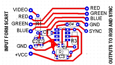
I designed this simple PCB which I fitted inside a small SCART plug to socket adaptor. This was the easiest technique to use as it came with wires already inside connecting the plug to a PCB then a SCART socket. Simply remove the socket, place the PCB into the old PCB space and wire a 9 Pin D type plug with quality multi way cable to the RGB, Sync and Ground points and feed it to your projector. Plug the SCART adaptor into your digibox/DVD player and enjoy a snyc locked picture.
Visit the Maplin website for chip connections at http://www.maplin.co.uk
Download the PCB design in PCB Wizard format by clicking here